Company: Philips Color Kinetics (PCK), Burlington MA, USA
Industry: Manufacturing of Smart Industrial Lighting Fixtures
Role: Product Design and Development Engineering Coop
Duration: July 2016 – December 2016
Overview: During my time at PCK, I was involved in multiple projects that required new product design or product upgrade design on CAD in SolidWorks. My designs were followed up by me consistently producing prototypes to validate them, using various processes such as 3D printing (FDM and Objet), laser cutting, using a lathe, using a mill, and using a hand-drill. In addition to prototyping, I verified my designs using computer based simulation models, such as FEA and CFD analysis on SolidWorks. As I was the only mechanical engineering intern in a cross functional product development team, I had to simultaneously work on several projects, however I will go over my 2 most interesting and challenging ones below
Project 1: Redesign of Rubber Gasket to Reduce Unaesthetic Deformation
Problem: During my time at Philips Color Kinetics, I worked on a project involving the redesign of a rubber gasket used for an accessory line of products. The gasket was to be used in compression between two metal components, however it deformed unaesthetically as shown.
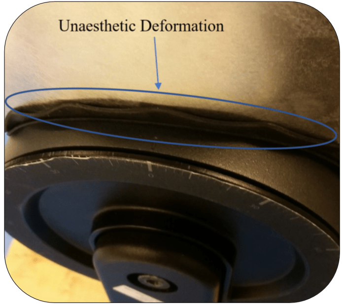
Unaesthetic Gasket Deformation Under Compression
I was tasked with redesigning the gasket in order to remove the curvy deformation seen in the Figure to the left. A key factor to consider in the redesign was that the tooling for the gasket was already in production, hence an easy to implement solution was required.
Solution: This was a particularly challenging project as I had to build my design variations using surface modeling on SolidWorks- a feature I was slightly unfamiliar with. Additionally, I was not able to prototype my design ideas in-house as we did not have rubber-prototyping capabilities. My approach was to use a deformation simulation analysis on SolidWorks to first represent identical results to the current gasket when being deformed. Once it mimicked the physical results, I used my simulation to evaluate my proposed designs and note if they minimized deformation. The following were my 5 proposed designs alongside the original, and the results from the simulation analysis:

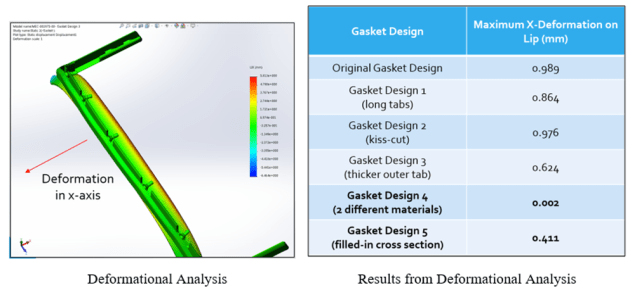
It was noted that redesign 4 had the most significant improvement, however since the tooling for the original gasket had already been made, a hybrid of redesign 3 and 5 were proposed to the supplier. The supplier agreed that this would be the easiest to implement solution, and the company moved forward with it.
Project 2: Unwanted Light Artifacts in Lighting Product
Problem: One of my projects was regarding a product line that had been halted due to irregularities in the field. They had noticed that light artifacts were seen when the product was placed against a wall, as shown.
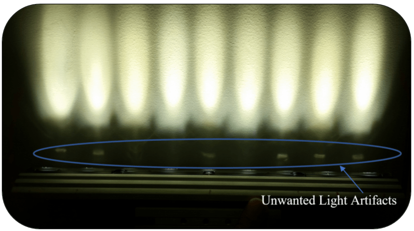
Observed Unwanted Light Artifacts
I was tasked with finding the reason behind the artifacts, and devising a solution to the problem.
Solution: Close inspection under a microscope showed the lenses used in the product were made through injection molding, and 2 tab features were on either side of the lens to allow for alignment. However, I noticed that one tab was the gate for the mold, and hence had a radius when it was machined, yet the other tab was part of the mold and did not have a radius. The tab without the radius was causing the artifacts, as when the product was flipped 180° against the wall, the artifacts disappeared. After discovering the root cause of the problem, I proposed 5 low-cost design solutions for “caps” that could be placed on top of the lenses. These would be easy to implement in the field, and I 3D printed them to test them on the product. The following were my designs:

Design Solution Variations for Artifact Problem
Testing showed design 4- which was a cover with a draft angle that would be press fitted over the lens- was the best solution, as it got completely rid of the artifacts as shown.

Observed Solution Showing No Light Artifacts
My manager agreed, and after I initially obtained a quote for injection molding from a supplier, he proceeded with the negotiations.
Skills Gained:
- I gained a great level of proficiency in SolidWorks through this coop. This included obtaining skills in surface modeling, image rendering (using Photo View 360), utilizing sheet metal modeling techniques, and refining my FEA and CFD simulation analysis.
- I learned data management techniques in SolidWorks through the use of ePDM. I was also given the responsibility to handle Engineering Change Orders (ECOs) and keep the CAD library up to date.
- I improved my understanding and use of 3D printers, laser cutters, and several machining tools. I developed experience in application driven prototyping and material selection.
- Since I was responsible for contacting various suppliers to get quotes on the parts I designed, I alleviated my GD&T skills, DFM and DFA skills, knowledge of various stages of the product life cycle, and also worked with various manufacturing processes, ranging from injection molding to die casting (in terms of designing for, and understanding the process of).
- I also worked closely with the machinist to get exposure into techniques such as MIG and TIG welding, soldering, and how to use force gauges.
